Automating Light-Map Creation in Maya
Intro
When using light-maps in Unreal texel density is key. However because these light-maps can often be quite small, doing this right can be a frustrating process which requires artists to layout their light-map UVs with the correct padding to avoid splitting pixels, creating shadow artifacts on objects in the scene. To make matters worse, the size of the object in the scene is the ultimate determining factor on what size light-map the object should use. This leaves the artists working in Maya without the proper context in which to make that decision, which leads to a back and forth between Maya and Unreal, or more commonly simply changing the light-map size in Unreal and hoping it doesn’t produce artifacts.
To improve this workflow, we can provide tools to estimate the light-map size based on the surface area of the object, as well as a suite of tools to help simplify their creation.
Overview
As this tool was requested by my Environment team, and was specifically requested to be a drop down menu, I worked within the constraints of Maya’s dropdown options. In future, I do think this UI would be better suited to it’s own dockable window.
The UI
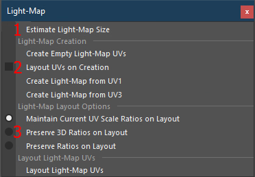
1. Estimate Light-Map Size will first take the surface area of the selected object, and then return a window with the estimated appropriate lightmap size for the object. This is also called behind the scenes to lay out the light-maps without the user needing to do anything. The main benefit here is the user can run this operation to get the appropriate light-map size, and can simply paste that value into the static mesh options in Unreal to set the correct light-map size when importing.
2. In the Light-Map Creation section we handle the creation of the light-map UV channel, with various options to fit our workflow which utilized multiple UV channels. Additionally, a checkable box determines if we do the entire layout process all at once on creation, making this a truly one-click operation.
3. In the Light-Map Layout Options section, we handle some options based on the needs for specific assets using radio-buttons. These options simply determine how we handle the layout of the UV shells.
4. Layout Light-Map UVs will run the layout process with the appropriate padding for the scale of the object by first estimating the lightmap size, then using the selected options to determine the needs of the asset before laying out the UVs.
The Demo
In the GIF above we see a quick example of three vastly different scale objects, and their estimated lightmap size. It is important to note that in order to estimate the light-map size, our transformations must be frozen.
In the GIF above we see a quick example of creating and laying out our light-map UVs from our existing UVs. In the first example, we see the process of duplicating UV 0 to UV 1, then laying them out. In the second example we select the “Layout on Creation” option, and we can also see that the UV’s retain their current scale ratios when laying out.
The Breakdown
The biggest benefit in this tool is the automatic estimation of the appropriate scale for the light-map. All of the other features are standard Maya options with fewer clicks, reducing the opportunity for human error by automatically applying the appropriate settings.
Interpreting the Ask
Because the Environment Team was spending a lot of time trying to get their light-maps laid out appropriately at the right scale, the ask was a relatively open-ended request to improve that workflow by providing some tools to help the artists make those decisions. Light-maps were universally hated and as such often complained about.
I interpreted this as an opportunity to eliminate as much of the human interaction as possible to reduce the frustration it was causing, so I set out with the following goals:
- Remove the guesswork from estimating the light-map size, and find a formula to produce consistent results.
- Remove the need to manually input values to lay out light-maps at the appropriate resolution.
- Reduce the amount of effort and input needed across the board.
The Formula
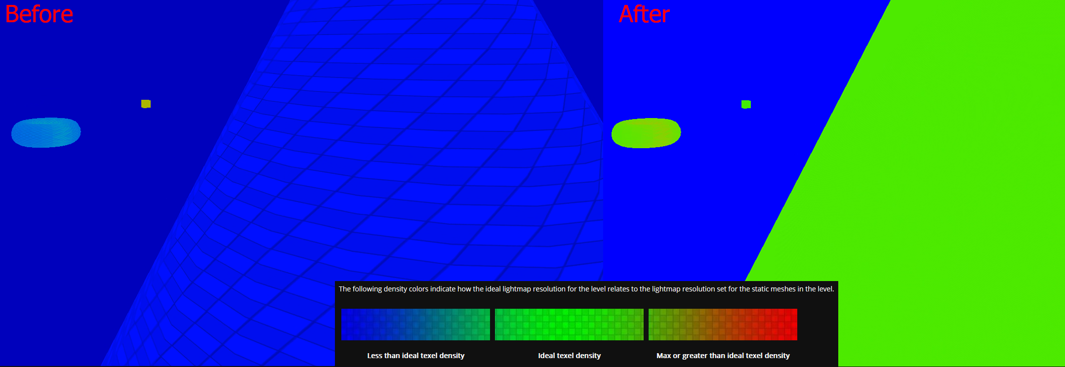
This was by far and away the most tricky part of figuring out this tool, and it is unfortunately not a one-size-fits-all solution for every project, because texture budgets vary and what worked for us may not be the right solution for others. Because there is no hard and fast rule on texel density for light-maps (likely because the visualizer is customizable, due to the fact that the light-map budget is different for every project), I first had to confirm with our lighting team and Environment lead that we were happy with the current settings. Once we had decided on our visualizer scale, I was able to set out on trying to get everything into the “green.”
In the end, using a series of 1m cubes scaled to different sizes and manually adjusting their lightmap sizes to figure out the appropriate surface-area-to-light-map-texture-size ratio. The formula that worked for us came out to:
SizeEstimate = 12(√(SurfaceArea/6)/10)
Because artists often worked with groups for a more manageable scene, I iterated over a list of objects, using cmds.polyEvaluate to retrieve the surface area of each of the object, then added them all together. From there, we used our formula.
Making it Useable
The above formula would consistently hit exact texture sizes in the correct circumstances (ie: a perfect cube with even measurements), but with real assets we would get odd numbers. To round to the nearest acceptable power of two texture, I defined a range of accepted light-map sizes, and we take the result of our formula and compare it to find the nearest power of two option, seen below.
Calculating Padding
Now that we know what texture size we are using the next step in automating this process is ensuring we applied the appropriate shell and tile padding values when laying out the UVs. To do this, we simply took our desired padding values, and divided them by the map size we found earlier.
Creating the UV Channel
All of the above is great, but without the proper UV channel we can’t actually do anything with this information. Because this tool was built in reaction to the process, I knew we already had some assets which would have light-map UV channels, and others would not. To accommodate the varying number of UV channels, and to ensure they were all in the appropriate channel, we check over our UV channels and make sure the correct channel is selected, before proceeding.
Laying Out the UVs
At this point, we have calculated everything we need to layout our UVs at the correct texel density with the correct padding, and we have ensured we have the correct channel created, populated, and selected. From here the last thing left is to lay out the UVs in the light-map channel. To do this, we simply pass the object, map size, shell and tile padding, and our selection from the UI for our scale ratios to pymel.other.u3dLayout. This will fail if we have non-manifold geometry, so we wrap this in a try/except and return a dialogue if something goes wrong.
In Action
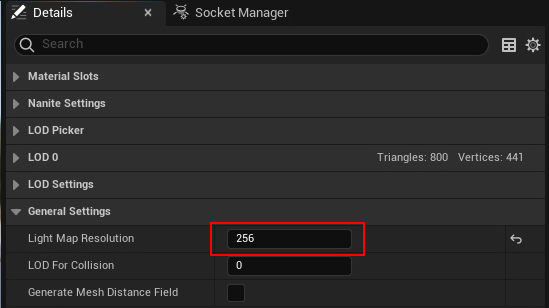
The last step in the process here is simply setting the appropriate light-map scale on the static mesh in Unreal. To do so, we simply must open up the static mesh details, and paste the copied value from the Light-Map Estimator under General Settings > Light Map Resolution.